5.0 Trajectory Tables
If you have purchased this manual in book form, and you have called one of Sierra’s ballistic technicians for trajectory information, the trajectory tables you may receive from our technicians are custom prepared for you using Sierra’s Infinity software. The basic elements of a trajectory and the information contained in the tables are described below.
We have included the most useful trajectory parameters (velocity, energy, drop, bullet path, wind drift and point blank range with the zero range to maximize it) in the Infinity tables. For each computed trajectory, they are tabulated for the user-selected muzzle velocity and shooting conditions.
This discussion uses an example of a popular rifle bullet to discuss each element of the baseline table and explain the important terms.
Trajectory: The trajectory of a projectile, in this case a rifle bullet, is the actual path that the projectile follows after leaving the muzzle. It is very important that this term be understood before using the tables. The trajectory of the bullet is shaped by many factors: gravity, altitude (air pressure), temperature, humidity, muzzle velocity, wind conditions, and the ballistic coefficient of the bullet itself. Although all of these have been discussed in much more detail in previous sections, the major contributors will be redescribed here as they affect the example trajectory.
![]()
The figure above illustrates the parts of a trajectory as they are discussed here and used in the tables. As soon as the bullet leaves the muzzle, gravity causes it to begin to fall away from its line of departure. This creates the drop discussed later. The line of departure is an imaginary line through the longitudinal centerline (Bore Centerline) of the bore and is the line upon which the bullet is launched. The significance of this line will be discussed as each element of the tables is discussed. Rz in the figure is the Zero Range where the trajectory crosses the line of sight on its downward path, and R is the Range of the bullet from the muzzle at each point along the trajectory. Muzzle velocity, air resistance (ballistic coefficient), and gravity are the major contributors to trajectory shaping.
Your Infinity tables are computed for the conditions defined in the “Trajectory Parameters” and “Environment Parameters” sidebars associated with theInfinity trajectory operations. The example we will describe below uses level fire, which means that the line between the gun muzzle and the target is level, and the line of departure is nearly level. In Figure 5.0-1, the elevation angle of the line of departure is greatly exaggerated for clarity. In practice, the elevation angle is a small fraction of a degree. The elevation angle of this line is determined by the sight height and the zero range. (Since the bullet begins falling immediately after it leaves the bore, it must be launched with a slightly upward direction so that it will fall back to the line of sight at the zero range).
Now, in order to illustrate the key elements in the Infinity tables, let’s discuss each element. The figure below shows the header for an Infinity trajectory table for the Sierra .257 inch diameter, 117 gr. Spitzer Boat Tail Bullet at a velocity that might be attained in a 25-06.
Trajectory for Sierra .257″ dia. 117 gr. SPT at 2900 Feet per Second
At an Elevation Angle of: 0 degrees Ballistic Coefficients of: 0.388
0.383
Velocity Boundaries (Feet per Second) of:
| 0.362 | 0.362 | 0.362 | |||
| 2500 | 1800 | 1800 |
1800
Wind Direction is: 3.0 o’clock and a Wind Velocity of 9.0 miles per hour
Wind Components are (miles per hour): Down Range: 0.0 Cross Range: 9.0 Vertical: 0.0 Altitude: 0 Feet with a Standard Atmospheric Model.
Temperature: 59°F
Data Printed in English Units
Figure 5.0-2
The header for a particular table documents the parameters used in computing the data table that follows after the header. The title, of course, is self-explanatory. The Elevation Angle defined as 0 degrees in the above example means that the baseline trajectory for this bullet was computed for level fire. The elevation angle permits computing a baseline trajectory for a shooting range that is not level. Although most shooting ranges are approximately level, some public and personal ranges are not.
The next two lines of the header must be taken together in the discussion. The first of these two lines defines the five Ballistic Coefficients which are used to compute the trajectory. The next line defines the velocity boundaries for the velocity ranges within which these Ballistic Coefficients are used. In this example, the 0.388 coefficient is used for computations when the bullet velocity is above 2500 feet per second, 0.383 is used for calculations when the bullet velocity is below 2500 feet per second but above 1800 feet per second, and 0.362 is used when the bullet velocity is below 1800 feet per second. As we have discussed previously, we provide for five Ballistic Coefficient values for our computations because our testing over the last 32 years has proven that a single Ballistic Coefficient does not accurately model the fit of the individual bullet drag to the G1 Drag Function. For this particular bullet we have found that three coefficients closely fit the bullet to the G1 Drag Function. The Ballistic Coefficients for Sierra bullets are all measured in controlled conditions in our underground test range.
The next two lines should also be examined together. The Wind Direction line documents the wind direction and speed that were entered in the “Environment Parameters” sidebar ofInfinity. The Wind Components line documents the actual downrange, crossrange and vertical wind components that have been resolved from the defined wind and used in the calculations. The next two lines define the atmospheric and temperature values that were used in the computations. The Altitude value is the altitude (or elevation) of the firing point above sea level, and the Temperature value is the temperature of the air at the firing point. The last line in the header documents the physical units used for the tabular material to follow.
Let’s discuss the basic elements of the trajectory table and what they represent. The figure below highlights the basic table elements.
The Range column documents the range distance for which the data in the remaining columns apply. Since the basic computations and data storage in Infinity are in one yard (or meter) increments, any integer printout interval value may be selected from 1 yard up to the maximum range. In figure 5.03 the printout interval has been chosen to be 50 yards, and this selection was entered in the “Trajectory Parameters” side bar.
| Range | Velocity | Energy | Momentum | Drop | Bullet Path | Wind Drift | Time of Flight | ||||||||
| (Yards) | (Ft/Sec) | (Ft/Lbs) | (Lb-Sec) | (inches) | (inches) | (inches) | (Seconds) | ||||||||
|
|
|
|
|
|
|
|
|
||||||||
| 0 | 2900.0 | 2184.5 | 1.51 | 0.0 | -1.5 | 0.0 | 0.000000000 | ||||||||
|
|
|
|
|
|
|
|
|
||||||||
| 50 | 2779.2 | 2006.3 | 1.44 | -0.53 | 0.67 | 0.18 | 0.052837693 | ||||||||
| 100 | 2661.6 | 1840.1 | 1.38 | -2.19 | 1.71 | 0.72 | 0.107990399 | ||||||||
| 150 | 2547.2 | 1685.3 | 1.32 | -5.07 | 1.53 | 1.65 | 0.165600200 | ||||||||
| 200 | 2434.6 | 1539.6 | 1.26 | -9.3 | 0.0 | 3.0 | 0.225830888 | ||||||||
| 250 | 2324.4 | 1403.3 | 1.21 | -14.99 | -2.99 | 4.79 | 0.288887624 | ||||||||
| 300 | 2216.9 | 1276.6 | 1.15 | -22.29 | -7.59 | 7.07 | 0.354968217 | ||||||||
| 350 | 2112.2 | 1158.9 | 1.10 | -31.36 | -13.96 | 9.86 | 0.424288238 | ||||||||
| 400 | 2010.4 | 1049.9 | 1.04 | -42.38 | -22.28 | 13.19 | 0.497081750 | ||||||||
| 450 | 1911.7 | 949.2 | 0.99 | -55.55 | -32.75 | 17.12 | 0.573599874 | ||||||||
| 500 | 1816.0 | 856.6 | 0.94 | -71.1 | -45.6 | 21.68 | 0.654111878 | ||||||||
| 550 | 1719.5 | 768.0 | 0.89 | -89.28 | -61.09 | 26.93 | 0.738988797 | ||||||||
| 600 | 1626.1 | 686.8 | 0.84 | -110.41 | -79.53 | 32.95 | 0.828709231 | ||||||||
| 650 | 1537.2 | 613.8 | 0.80 | -134.83 | -101.25 | 39.79 | 0.923603742 | ||||||||
| 700 | 1453.4 | 548.7 | 0.76 | -162.94 | -126.65 | 47.5 | 1.023986006 | ||||||||
| 750 | 1375.0 | 491.1 | 0.71 | -195.15 | -156.17 | 56.12 | 1.130134794 | ||||||||
| 800 | 1302.6 | 440.8 | 0.68 | -231.97 | -190.29 | 65.69 | 1.242270846 | ||||||||
| 850 | 1237.0 | 397.5 | 0.64 | -273.92 | -229.53 | 76.22 | 1.360513639 | ||||||||
| 900 | 1178.7 | 360.9 | 0.61 | -321.54 | -274.46 | 87.72 | 1.484836153 | ||||||||
| 950 | 1128.0 | 330.5 | 0.59 | -375.42 | -325.64 | 100.15 | 1.615043409 | ||||||||
| 1000 | 1084.8 | 305.7 | 0.56 | -436.14 | -383.66 | 113.46 | 1.750789074 | ||||||||
| Figure 5.0-3 | |||||||||||||||
The Velocity column is the speed with which the bullet is moving at any given point. In our trajectory table, it is the remaining velocity at the printout range. Remaining velocity is the velocity left after the bullet has been launched with the Muzzle Velocity and has then decelerated (slowed down) due to air resistance while traveling the distance to the printout range. The rate at which the bullet slows down is related to its ballistic coefficient(s) and the properties of the air (temperature, humidity, barometric pressure) over the path the bullet travels.
The Energy column, as typically used in ballistics tables, is Kinetic Energy. Without getting involved in whether Kinetic Energy or Momentum provides the killing power and what the mechanisms are, we’ll discuss both.
The Kinetic Energy of a bullet is based on the mass of the bullet and the velocity with which it is traveling. The mass is not identical to the bullet weight so the bullet weight must be converted to mass before we can use it.
The mathematical formula for the mass of a bullet is:
where: w = bullet weight in grains and g = 32.174 ft/sec2 (acceleration due to gravity)
![]()
(The factor of 7000 converts bullet weight from grains to pounds) The Kinetic Energy of the bullet can then be found from the formula:
where: m = mass of the bullet and: v = the remaining velocity
![]()
The Momentum column is included as an additional measure of effectiveness. Momentum is calculated using the formula:
where: m = mass of the bullet and: v = the remaining velocity

Drop, as it is used in ballistic computations, is really an intermediate parameter. That is, it is useful to calculate other parameters. The drop of the bullet is the vertical distance of the bullet referenced to the line of departure from the bore. The following figure illustrates drop when the line of departure is horizontal. When the line of departure is not horizontal (tilted upward or downward), drop is still defined as the vertical distance between the bullet and the line of departure at any point in the trajectory. Drop is used in the computations of bullet path, but otherwise it has meaning primarily in a direct comparison of two bullets as to the shape of their trajectories.
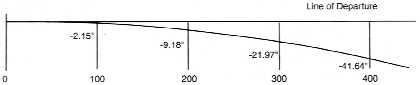
Figure 5.0-4
The values in the Bullet Path column are the position of the bullet with respect to the shooter’s line of sight through the gunsights. For the average shooter, bullet path is one of the most useful parameters in the tables. Bullet path values are based upon the sight height (distance of the line of sight above the bore centerline at the gun) and the desired zero range. These two points determine the line of sight with respect to the gun and permit an accurate calculation, using the drop, of the bullet position with respect to the line of sight. The sight height above the bore centerline can be measured for your specific firearm and entered on the Infinity “Trajectory Parameters” sidebar. We use 1.5 inches for the sight height for rifles and handguns with telescope sights and 0.8 inches for rifles with iron sights and most handguns as default values for sight height. Figure 5.0-5 illustrates the bullet path. This rifle has a sight height of 1.5 inches and is zeroed at about 220 yards. The bullet path is 1.5 inches below the line of sight at the muzzle, 1.68 inches above the line of sight at 100 yards, 7.45 inches low at 300 yards, and 21.78 inches below the line of sight at 400 yards.
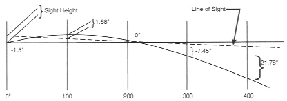
Figure 5.0-5
Wind Drift values are shown for the resolved value of crosswind. The deflection of the bullet due to crosswind is related to the crosswind velocity (or crosswind component of a wind from any direction) and the time of flight of the bullet. In this example, we used a 3 o’clock wind direction (crosswind only blowing from right to left across the shooter’s line of sight to the target) so there is little impact on the drop or bullet path. (There could be an impact at the longer ranges due to the increased time of flight over the slightly longer flight path.) If we use a quartering wind (1.30 o’clock for example) there will be an impact on the drop (increased drop), time of flight (also increased), and bullet path (bullet shooting lower) due to the headwind component.
The Time of Flight column shows the flight time to the range distance in the range column.
Now, let’s discuss Point Blank Range and the Infinity printout features related to it. The figure below shows a graphical view of Point Blank Range.
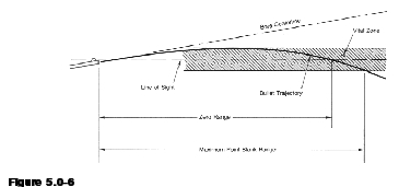
Point Blank Range (PBR) is that range distance out to which a shooter can always hold directly on his target, with no compensation for drop, and expect a hit within the vital zone.
Maximum Point Blank Range (MPBR) refers to the maximum range for which the firearm can be zeroed such that the bullet will neither rise above the line of sight farther than one-half the vital zone height nor fall below the line of sight more than one-half the vital zone height.
“Vital Zone” refers to that area within which an animal may be hit and the hit is quickly fatal. In a deer-sized animal, that zone is approximately 10 inches high and centered on the heart/lung area. On a prairie dog or ground squirrel the vital zone is much smaller, typically 2 to 4 inches in height. The concept applies equally well to the metallic silhouette and other games. The
Point Blank Range and the Maximum Point Blank Range values are printed as a result of running either the Point Blank Range or the Maximum Point Blank Range Operation in the Operations menu of Infinity. Both quantities represent the maximum range that you can hold directly on the target and hit within the vital zone. The difference is that, if your zero range is less than the zero range which maximizes the point blank range (MPBR zero), the bullet path at ranges closer than the zero range will not reach a value as high as one-half the vital zone height above the line of sight. So, your PBR is less than it could be for the game you are hunting. Running the Maximum Point Blank Range Operation in Infinity will tell you where to zero your gun to maximize the point blank range, as the example below shows.
Note that in the example below, the bullet path is computed for the Maximum Point Blank Range Zero even though the MPBR zero doesn’t lie at a printout range point. If you wish to maximize your point blank range, and you are sighting in on a 100-yard range, simply center your group about 4.02 inches higher than your aimpoint. (3.5 to 4.5 inches might be close enough for most hunters!). If you have a 200-yard range, you would center your group about 4.6 inches above your aimpoint. Then you can take full advantage of the 343 yard PBR of your rifle and load for deer.
Calculation of Maximum Point Blank Range for a Vital Zone of: 10 inches Maximum Point Blank Range is 343. Set Zero at 292
Trajectory for Sierra .257” dia. 117 gr. SPT at 2900 Feet per Second
At an Elevation Angle of: 0 degrees
Ballistic Coefficients of: 0.388 0.383 0.362
0.362 0.362
Velocity Boundaries (feet per second) of: 2500 1800 1800
1800
Wind Direction is: 3.0 o’clock and a Wind Velocity of: 9.0 miles per hour
Wind Components are (feet per sec): Downrange: 0.0 Cross Range: 0.0 Vertical: 0.0
Altitude: 0 Feet with a Standard Atmospheric Model. Temperature: 59 F
Data Printed in English Units
| Range | Velocity | Energy | Momentum | Drop | Bullet Path | Wind Drift | Time of Flight | ||||||||
| (Yards) | (Ft/Sec) | (Ft/Lbs) | (Ft-Lbs) | (inches) | (inches) | (inches) | (Seconds) | ||||||||
| 0 | 2900.0 | 2184.5 | 1.51 | 0.0 | -1.5 | 0.0 | 0.000000000 | ||||||||
| 50 | 2779.2 | 2006.3 | 1.44 | -0.53 | 1.82 | 0.45 | 0.052837693 | ||||||||
| 100 | 2661.6 | 1840.1 | 1.38 | -2.19 | 4.02 | 1.83 | 0.107990399 | ||||||||
| 150 | 2547.2 | 1685.3 | 1.32 | -5.07 | 4.99 | 4.2 | 0.165600200 | ||||||||
| 200 | 2434.6 | 1539.6 | 1.26 | -9.3 | 4.62 | 7.62 | 0.225830888 | ||||||||
| 250 | 2324.4 | 1403.3 | 1.21 | -14.99 | 2.78 | 12.18 | 0.288887624 | ||||||||
| 300 | 2216.9 | 1276.6 | 1.15 | -22.29 | -0.67 | 17.95 | 0.354968217 | ||||||||
| 350 | 2112.2 | 1158.9 | 1.10 | -31.36 | -5.88 | 25.03 | 0.424288238 | ||||||||
| 400 | 2010.4 | 1049.9 | 1.04 | -42.38 | -13.05 | 33.51 | 0.497081750 | ||||||||
| 450 | 1911.7 | 949.2 | 0.99 | -55.55 | -22.36 | 43.49 | 0.573599874 | ||||||||
| Figure 5.0-7 | |||||||||||||||